Level 00
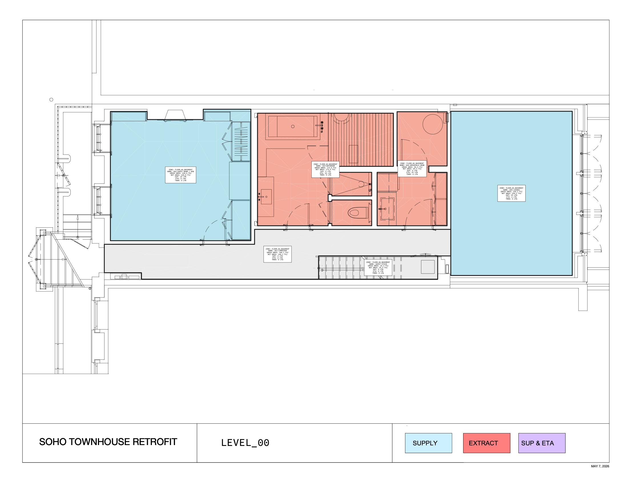
01
An airtight, low-energy building in this climate should include dedicated mechanical ventilation with heat recovery in order to deliver enough fresh air for good indoor air quality (IAQ) in all seasons.
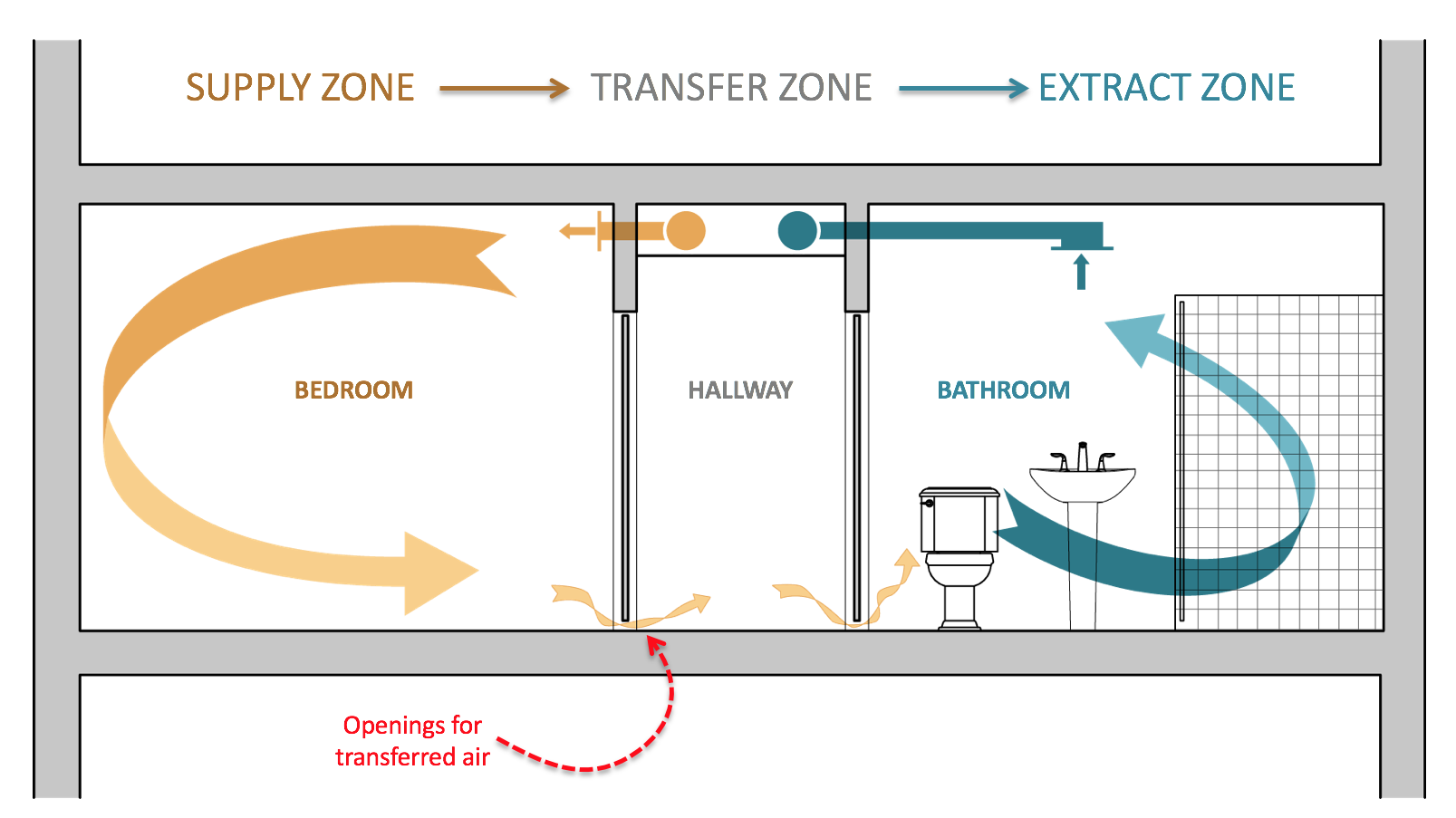
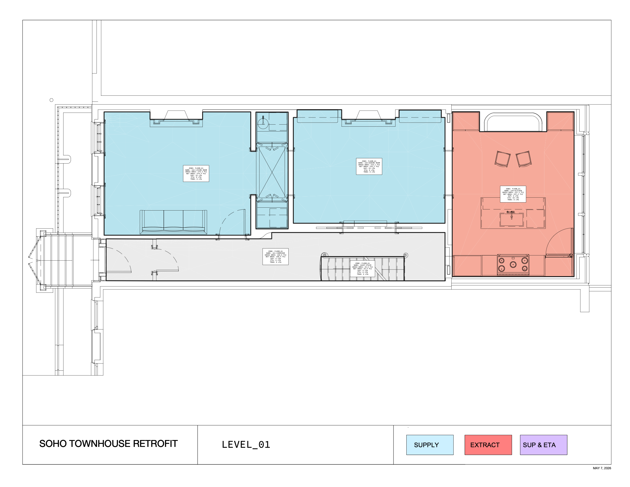
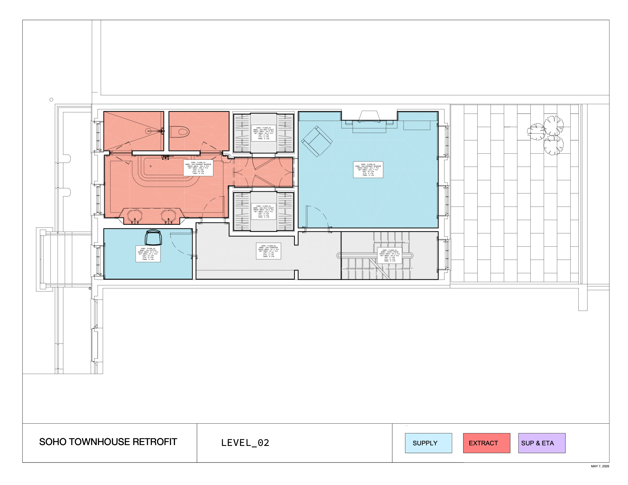
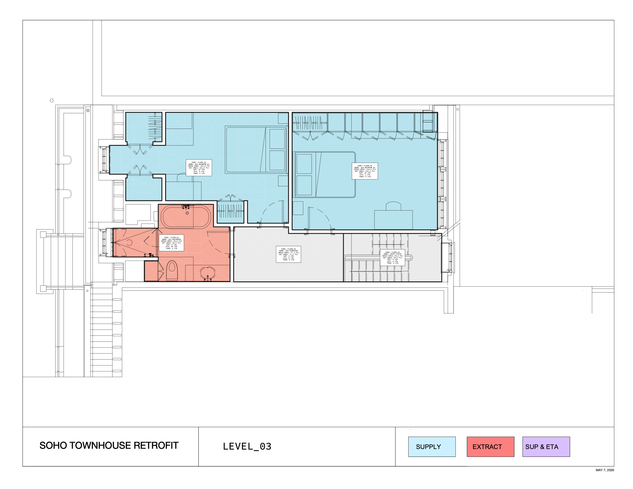
It is important not to over-ventilate a building in winter. Otherwise, indoor air can become too dry, with associated health and comfort concerns. To reduce airflow rates while still maintaining good indoor air quality, we recommend a Supply-Transfer-Extract configuration rather than supplying and extracting from each individual room.
Supply air should be provided to bedrooms and living spaces, while extract air should be drawn from bathrooms, the kitchen, and any storage spaces. Transfer openings, such as door undercuts or transfer grilles, should be provided between supply and extract spaces.
This configuration reduces the potential for duct-borne sound transmission between spaces, ensures good mixing of fresh air, and reduces the size, complexity, and cost of the required ducting.
It is critically important that the fresh-air ventilation system be installed so that it is completely independent of the heating and cooling system. There is no effective method of combining the fresh-air ducting with heating/cooling ducting, so planning should allocate sufficient space for both ducting systems.
02
The fresh-air system should be sized around the room-by-room supply, transfer, and extract strategy rather than around a single whole-building ventilation rate. The table below keeps the modeled airflow assumptions visible for design coordination and commissioning.
| Room | Areaft2 | Volumeft3 | Supply highcfm | Extract highcfm | Supply medcfm | Extract medcfm |
|---|---|---|---|---|---|---|
| 000ST-STAIR | 35.3 ft2 | 289 ft3 | 0 cfm | 0 cfm | 0 cfm | 0 cfm |
| 001-CORRIDOR | 149 ft2 | 1,223 ft3 | 0 cfm | 0 cfm | 0 cfm | 0 cfm |
| 002-GUEST ROOM / DEN | 227 ft2 | 1,861 ft3 | 25 cfm | 0 cfm | 18.8 cfm | 0 cfm |
| 003-BATHROOM | 173 ft2 | 1,416 ft3 | 0 cfm | 25 cfm | 0 cfm | 18.8 cfm |
| 004-HOUSEHOLD ROOM | 84.5 ft2 | 693 ft3 | 0 cfm | 25 cfm | 0 cfm | 18.8 cfm |
| 005-LOUNGE | 254 ft2 | 2,085 ft3 | 25 cfm | 0 cfm | 18.8 cfm | 0 cfm |
| 100ST-STAIR | 25.5 ft2 | 209 ft3 | 0 cfm | 0 cfm | 0 cfm | 0 cfm |
| 101-CORRIDOR | 168 ft2 | 1,382 ft3 | 0 cfm | 0 cfm | 0 cfm | 0 cfm |
| 102-LIVING ROOM | 274 ft2 | 2,250 ft3 | 25 cfm | 0 cfm | 18.8 cfm | 0 cfm |
| 103-DINING ROOM | 210 ft2 | 1,723 ft3 | 25 cfm | 0 cfm | 18.8 cfm | 0 cfm |
| 104-KITCHEN | 237 ft2 | 1,945 ft3 | 0 cfm | 50 cfm | 0 cfm | 37.5 cfm |
| 200-CORRIDOR | 87.1 ft2 | 714 ft3 | 0 cfm | 0 cfm | 0 cfm | 0 cfm |
| 200ST-STAIR | 59.4 ft2 | 487 ft3 | 0 cfm | 0 cfm | 0 cfm | 0 cfm |
| 201-OFFICE | 57.1 ft2 | 468 ft3 | 25 cfm | 0 cfm | 18.8 cfm | 0 cfm |
| 203-HER CLOSET | 29.5 ft2 | 242 ft3 | 0 cfm | 0 cfm | 0 cfm | 0 cfm |
| 204-PRIMARY BEDROOM | 190 ft2 | 1,561 ft3 | 0 cfm | 50 cfm | 0 cfm | 37.5 cfm |
| 205-HIS CLOSET | 29.5 ft2 | 242 ft3 | 0 cfm | 0 cfm | 0 cfm | 0 cfm |
| 206-PRIMARY BEDROOM | 202 ft2 | 1,654 ft3 | 25 cfm | 0 cfm | 18.8 cfm | 0 cfm |
| Total | 3,663 ft2 | 27,834 ft3 | 830 cfm | 830 cfm | 150 cfm | 150 cfm |
03
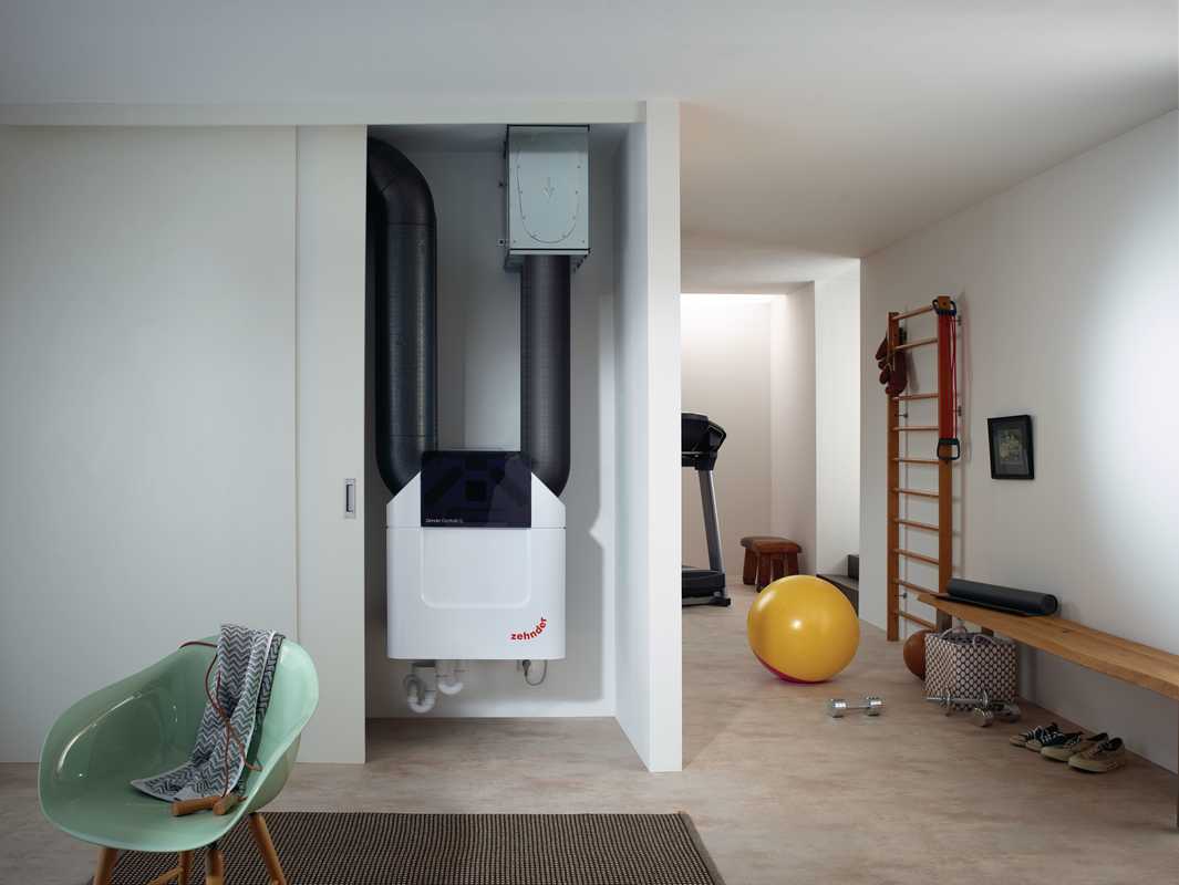
For this building, we recommend that each unit have its own high-performance H/ERV with better than 75% heat recovery. The Zehnder America ComfoAir Q600 ERV would be a good selection and provide excellent indoor air quality while minimizing energy consumption and occupant comfort issues. These units are outfitted with excellent air filtration, MERV 13 by default, which will be critical to ensuring clean and healthy indoor air.
The values used in this analysis are assumed only. Zehnder America should be retained to fully design, specify, and balance the system after installation. This is critical for proper operation and required for all high-performance buildings. The balancing service will normally come standard with Zehnder America packages, but this should be verified in this case.
Prior to occupancy, the fresh-air system should be tested and balanced to ensure good air mixing and adequate supply to all living spaces. The HRV vendor should provide this balancing as part of their services.
04
In addition to the modeled performance thresholds, in order to certify a building as a Passive House building, projects would have to comply with the following design requirements. Whether the project achieves full Passive House certification or not, the following design guidelines are recommended for all projects:
05
Kitchen venting should be provided at the lowest rate that satisfies regulations. For gas cooking, this flow rate will be specified by code. For electric cooking, limit exhaust hood airflow to 200-400 cfm maximum through the selection of an appropriately sized hood. The Home Ventilation Institute (HVI) specifies a minimum of 40 cfm and recommends 100 cfm per linear foot of range. For effective kitchen venting, sizing and placement of the hood can be more important than the air flow rate, as sizing and placement effect the capture efficiency of the hood. Hoods should be as low as practical, extend beyond the range by approximately six inches at the sides and be as deep as possible without interfering with use of the range.
In order to properly vent any exhaust air appliances (clothes dryers, kitchen hoods, etc..) in an air-tight home, a dedicated makeup air system may be necessary. This is especially true of homes with combustion appliances (e.g. wood stoves/fireplaces) located indoors. In this scenario, makeup air from an automatic makeup air fan is used to balance out the exhausted air.
Note that for most cases we do NOT recommend this strategy as it is costly, complicated, and adds considerable complexity to the envelope construction (insulation, air-sealing) and represents a significant energy penalty to heat/cool the makeup air.
Wherever possible, the use of all-electric systems should be considered, and combustion appliances should be installed only in outdoor locations (porches, decks, etc.).
Heating / Cooling of any outdoor makeup air may be needed once it enters the habitable space. Self-closing (magnetic) dampers should be included on all ducting to prevent air infiltration / exfiltration when the appliances are not in use. In order not to compromise occupant comfort when makeup air is being supplied to the home, a high output heating element will need to be sized and installed to heat the incoming volume of air to a comfortable temperature.
There are several good, self-modulating makeup air system (MUAS) and corresponding makeup air heater (MUAH) which could be a good fit for this project:
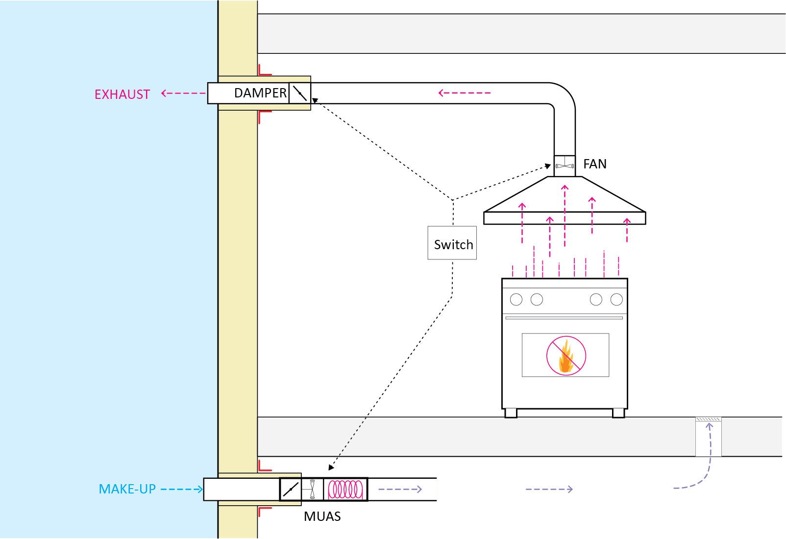
Proper commissioning and continued maintenance of the makeup air system is critical to the safe operation of the home, particularly when combustion appliances are present.
Several things should be kept in mind when configuring such a system:
06
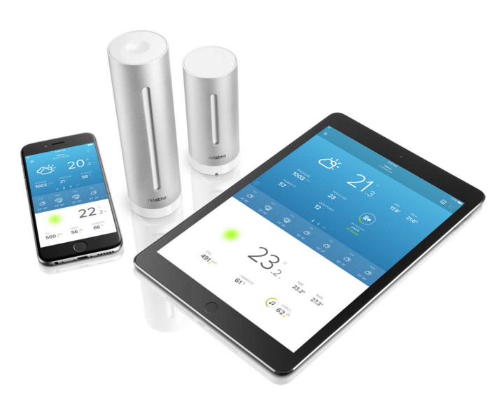
There are several systems available for monitoring temperature, RH, CO2, and other environmental conditions. We strongly recommend installing a system of some form in order to successfully commission the home and correct any issues with indoor comfort over the first year. Environmental monitoring systems are relatively low cost, and we recommend two possible systems: the Wireless Sensor Tag by Cao Gadgets LLC, and the Netatmo weather station. Both systems upload data to the internet over a wireless network and data can be accessed online. Note that this requires a wireless network to be in operation at the home at all times. Other monitoring systems are available from newer platforms such as Ecobee.
The Wireless Tag system is less costly, but cannot monitor CO2. For this reason, we would prefer the Netatmo system.
More information can be found at:
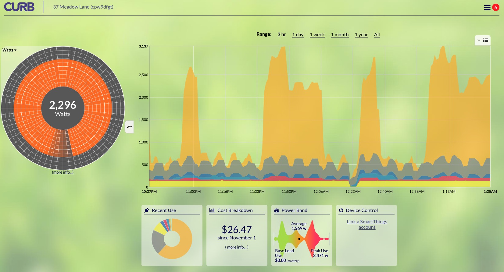
To really understand a home’s energy use, a branch-circuit monitoring system is the way to go. Monitoring each electrical circuit, especially in the first months of a project’s operation, can help identify systems that are working incorrectly and using more energy than they should. For projects with new electrical services, it makes sense to install a load center designed to do just that. A number of manufacturers offer load centers with integrated branch-circuit monitoring that can integrate with other smart controls, such as switching and dimming. Real-time and historical energy-use data are available through the product app.
More information can be found at:
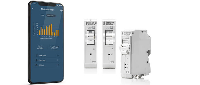
Other options are available for integration with more typical circuit breaker panels. Systems such as the Curb energy monitor, the Emporia Vue, and the eGauge provide customizable, real-time monitoring of electrical usage. The web/app-based interface displays detailed information about the home’s energy usage and can help to fine-tune energy conservation measures.
More information can be found at: